This is a small, but annoying thing about WordPress. They obviously didn’t consider the “0x” hexadecimal notation. What they did consider, was that if someone says “2x2″ that surely means “2 times 2″, so why not making that “x” in the middle fancy? Well, maybe because that makes “0x123″, which is a hexadecimal number, look weird.
The fix is in the core PHP files of WordPress, so this probably needs to be fixed every time WordPress is updated.
In wp-includes/formatting.php, in the wptexturize() function, probably around lines 50-51 there’s something like:
$dynamic_characters = array('/\'(\d\d(?:’|\')?s)/', '/(\s|\A|")\'/', '/(\d+)"/', '/(\d+)\'/', '/(\S)\'([^\'\s])/', '/(\s|\A)"(?!\s)/', '/"(\s|\S|\Z)/', '/\'([\s.]|\Z)/', '/\b(\d+)x(\d+)\b/');
$dynamic_replacements = array('’$1','$1‘', '$1″', '$1′', '$1’$2', '$1“$2', '”$1', '’$1', '$1×$2')
The last entry in both arrays replaces two numbers with an “x” between them with a fancy “times” symbol (Unicode character #215). So just remove those two entries from both arrays (marked in red above). Remove the commas as well, of course.
Maybe the 100% correct way to fix this, is to use a better regular expression, instead of ‘/\b(\d+)x(\d+)\b/’. I’m not sure about regular expressions in PHP, but in Perl I would try ‘/\b([1-9]\d*)x(\d+)\b/’, so it wouldn’t match the “0x” notation. It wouldn’t match “02 x 2 = 4″ or any other number prefixed with zeros, but this is not something normal people write anyhow.
It may help investigating the interrupt descriptors. For a 2.6.38 kernel, putting this in a kernel module load supplies some information (includes, declarations and code mixed below. Organize properly in your own module)
#include <linux/irq.h>
#include <linux/interrupt.h>
#include <asm/irq.h>

int i;
struct irq_desc *desc;

for_each_irq_desc(i, desc) {
 if (!desc)
   continue;
 printk(KERN_INFO "%d: status=%08x, chip=%08x, handle_irq=%08x\n",
        i, (u32) desc->status, (u32) desc->chip, (u32) desc->handle_irq );
 }
This dumps some meta information about all possible IRQs on the system. Also be sure to look at /proc/interrupts.
Have a look in include/linux/irq.h for the meaning of the flags in desc->status and possibly include/linux/irqdesc.h for the irq_desc structure.
request_irq() may very well fail because the IRQ_NOREQUEST flag was set in status. On ARM architecture, this can be fixed by calling set_irq_flags(irq, IRQF_VALID) assuming that you have a fairly good idea of what you’re doing.
Note that set_irq_chip_and_handler() is usually called before validating an IRQ, so that Linux knows what to do with the interrupt as it happens. Looking at chip and handle_irq in the dump may give a clue about how necessary this is. Searching for the value of handle_irq in /proc/kallsyms (with a simple grep) tells who handles each interrupt.
The “chip” structure is a container for information and methods specific to the interrupt’s owner. In old days, these belonged to peripheral chips, but a “chip” is many times just a group of interrupts having a common way of handling them (setting trigger type, masking etc.).
A final note: It looks like the API is changing vividly in this area, so don’t expect things to be exactly the same on other kernels.
What we have here
As one can guess from my notes about the i.MX51′s external bus and the oscilloscope shots I’ve published, I made myself a small dissection kit for watching the bus’ lines activity with a digital oscilloscope.
This is a good time to mention, that the kit was done quickly and dirty, so the code below should not be taken as an example of proper coding for FPGA nor the Linux kernel. Seriously, this is just lab code.
Anyhow, this little kit consists of two parts
- Verilog code and UCF for programming the FPGA. Except for blinking the LED (at 1 Hz), it also wires all EIM-bus related signals to the FPGA pin headers on the development board, so they can be sampled easily with oscilloscope’s probes. You can download the bitfile directly if your board has the LX9 FPGA, or implement it from the sources below.
- A kernel module, which performs a single bus operation when it’s loaded. It’s explained further below. If you happen to be running on a 2.6.38.1 Linux kernel on your board (in particular the 2.6.38.1 which comes preloaded on the board), you may try using the precompiled kernel module. Or do it the “right way” and compile the module from the sources below.
The Verilog code below pretty much explains itself. And as the comments in the UCF say, the “debug_pins_outer” pin vector runs from pin #38 downwards continuously, on even pins only, on the outer FPGA pin header. This may sound complicated, but it simply means that out of the two rows of this pin header, only the row reached easily with a probe is used. And since pin #40 (in the corner) isn’t attached to the FPGA, debug_outer_pins[0] is connected to pin #38, debug_outer_pins[1] to #36 and so on.
As for the “debug_pin_inner” it goes more or less the same. Going from pin #3 for debug_inner_pins[0] and up on odd pin numbers, only the inner pin row of the inner pin header is used for easy physical access.
This may look like a weird choice of pin assignments, but this was the only way to get the vectors assigned on the pin headers without any gaps between them, so it’s easy to reach any signal in the vectors just by counting pins on the pin header.
Please make sure that the two “FPGA bank” jumpers are installed on your board, or nothing will appear on the pin headers. These jumpers were installed on the board as I got it, so just check it’s OK.
It’s also worth to note that debug_pins_outer[4] happens to be connected to a pin which is shared with a pushbutton on the board. Since the line is pulled up with a 10 kOhm resistor, this line may have some timing skew.
Simple use
Assuming that both the bitfile and the kernel module are in the currect directory, first load the FPGA if you haven’t done so already:
# load_fpga armaled.bit
A green LED should start blinking as a result of this. Note that according to Armadeus’ wiki page on the FPGA loader, armaled.bit should not be on the on-board flash. Copy it to /tmp first (which is on RAM) or load it from an net drive (e.g. NFS) like I did.
And then, to kick off a bus cycle, load the module and catch it on the oscilloscope:
# insmod eimtest.ko
And then unload the module, so you can load it again for the next try:
# rmmod eimtest
The relevant bus parameters can be set directly when loading the module. For example, to add an extra bus wait state, disable continuous bus clock, run at 1/4 bus rate and use bus address OxABC0, go:
# insmod eimtest.ko WSC=2 BCD=3 BCM=0 addr=0xabc0
A list of kernel module parameters, which in turn changes the bus parameters, is found in the kernel module’s source. Anything declared with “module_param” can be set. The defaults are given in the variable declarations. Setting the address and data is also possible, but be sure not to exceed the address 0xFFFC, or you’ll get a kernel oops. Also note that addresses not aligned to 32-bit words will produce several bus cycles.
The Verilog code
Note that the direct wire connections have a variable delay. This results in some unknown skew (1-2ns, I suppose) between the outputs.
module armaled
 (
 input ext_clk,
 output reg led,
 output irq,

 input [15:0] imx51_da,

 input imx51_cs1,
 input imx51_cs2,
 input imx51_adv,
 input imx51_we,
 input imx51_eb0,
 input imx51_eb1,
 input imx51_oe,
 input imx51_dtack,
 input imx51_wait,
 input imx51_bclk,
 input imx51_clko,

 output [13:0] debug_pins_inner,
 output [12:0] debug_pins_outer
 );

 reg [27:0] counter;

 assign     irq = 0;

 assign     debug_pins_outer[0] = imx51_bclk;
 assign     debug_pins_outer[1] = imx51_clko;
 assign     debug_pins_outer[2] = imx51_oe;
 assign     debug_pins_outer[3] = imx51_cs1;
 assign     debug_pins_outer[4] = imx51_cs2;
 assign     debug_pins_outer[5] = imx51_adv;
 assign     debug_pins_outer[6] = imx51_we;
 assign     debug_pins_outer[7] = imx51_eb0;
 assign     debug_pins_outer[8] = imx51_eb1;
 assign     debug_pins_outer[9] = imx51_dtack;
 assign     debug_pins_outer[10] = imx51_wait;
 assign     debug_pins_outer[12:11] = imx51_da[15:14];

 assign     debug_pins_inner = imx51_da[13:0];

 always @(posedge ext_clk)
 begin
 if (counter >= 47500000)
 begin
 led <= !led;
 counter <= 0;
 end
 else
 counter <= counter + 1;
 end

endmodule
The UCF file
NET "ext_clk" TNM_NET = "TN_ext_clk";
TIMESPEC "TS_ext_clk" = PERIOD "TN_ext_clk" 10.4 ns HIGH 50 %;

NET "led" LOC="G14" | IOSTANDARD=LVCMOS33;# IO_L41P_GCLK9_IRDY1_M1RASN_1
#NET "button" LOC="G15" | IOSTANDARD=LVCMOS33;# IO_L41N_GCLK8_M1CASN_1
NET "ext_clk" LOC="N8" | IOSTANDARD=LVCMOS33;# = BCLK, IO_L29P_GCLK3_2
NET "irq" LOC="P3" | IOSTANDARD=LVCMOS33;# FPGA_INITB

# Debug pins.

# The "inner" set starts from pin #3, running on odd pins only (effectively
# covering the pins convenient to attach a scope's probe to)

NET "debug_pins_inner[0]" LOC="L2" | IOSTANDARD=LVCMOS33;# IO_L39P_M3LDQS_3
NET "debug_pins_inner[1]" LOC="J2" | IOSTANDARD=LVCMOS33;# IO_L41P_GCLK27_M3DQ4_3
NET "debug_pins_inner[2]" LOC="K4" | IOSTANDARD=LVCMOS33;# IO_L43P_GCLK23_M3RASN_3
NET "debug_pins_inner[3]" LOC="K5" | IOSTANDARD=LVCMOS33;# IO_L45P_M3A3_3
NET "debug_pins_inner[4]" LOC="C2" | IOSTANDARD=LVCMOS33;# IO_L83P_3
NET "debug_pins_inner[5]" LOC="D4" | IOSTANDARD=LVCMOS33;# IO_L53P_M3CKE_3
NET "debug_pins_inner[6]" LOC="K3" | IOSTANDARD=LVCMOS33;# IO_L40P_M3DQ6_3
NET "debug_pins_inner[7]" LOC="H3" | IOSTANDARD=LVCMOS33;# IO_L42P_GCLK25_TRDY2_M3UDM_3
NET "debug_pins_inner[8]" LOC="G2" | IOSTANDARD=LVCMOS33;# IO_L44P_GCLK21_M3A5_3
NET "debug_pins_inner[9]" LOC="F3" | IOSTANDARD=LVCMOS33;# IO_L46P_M3CLK_3
NET "debug_pins_inner[10]" LOC="D3" | IOSTANDARD=LVCMOS33;# IO_L54P_M3RESET_3
NET "debug_pins_inner[11]" LOC="E2" | IOSTANDARD=LVCMOS33;# IO_L52P_M3A8_3
NET "debug_pins_inner[12]" LOC="K13" | IOSTANDARD=LVCMOS33;# IO_L44P_A3_M1DQ6_1
NET "debug_pins_inner[13]" LOC="H13" | IOSTANDARD=LVCMOS33;# IO_L42P_GCLK7_M1UDM_1

# The "outer" set starts from pin #38, running on even pins only (effectively
# covering the pins convenient to attach a scope's probe to). Note that the
# vectors runs from high board pin number to low.

NET "debug_pins_outer[0]" LOC="B15" | IOSTANDARD=LVCMOS33;# IO_L1N_A24_VREF_1
NET "debug_pins_outer[1]" LOC="C15" | IOSTANDARD=LVCMOS33;# IO_L33N_A14_M1A4_1
NET "debug_pins_outer[2]" LOC="D15" | IOSTANDARD=LVCMOS33;# IO_L35N_A10_M1A2_1
NET "debug_pins_outer[3]" LOC="E15" | IOSTANDARD=LVCMOS33;# IO_L37N_A6_M1A1_1
NET "debug_pins_outer[4]" LOC="G15" | IOSTANDARD=LVCMOS33;# IO_L41N_GCLK8_M1CASN_1
NET "debug_pins_outer[5]" LOC="J15" | IOSTANDARD=LVCMOS33;# IO_L43N_GCLK4_M1DQ5_1
NET "debug_pins_outer[6]" LOC="L15" | IOSTANDARD=LVCMOS33;# IO_L45N_A0_M1LDQSN_1
NET "debug_pins_outer[7]" LOC="G12" | IOSTANDARD=LVCMOS33;# IO_L30N_A20_M1A11_1
NET "debug_pins_outer[8]" LOC="F12" | IOSTANDARD=LVCMOS33;# IO_L31N_A18_M1A12_1
NET "debug_pins_outer[9]" LOC="H11" | IOSTANDARD=LVCMOS33;# IO_L32N_A16_M1A9_1
NET "debug_pins_outer[10]" LOC="G13" | IOSTANDARD=LVCMOS33;# IO_L34N_A12_M1BA2_1
NET "debug_pins_outer[11]" LOC="J13" | IOSTANDARD=LVCMOS33;# IO_L36N_A8_M1BA1_1
NET "debug_pins_outer[12]" LOC="K11" | IOSTANDARD=LVCMOS33;# IO_L38N_A4_M1CLKN_1

# i.MX51 related pins

NET "imx51_cs1" LOC="R11" | IOSTANDARD=LVCMOS33;# EIM_CS1
NET "imx51_cs2" LOC="N9" | IOSTANDARD=LVCMOS33;# EIM_CS2
NET "imx51_adv" LOC="R9" | IOSTANDARD=LVCMOS33;# EIM_LBA
NET "imx51_we" LOC="R6" | IOSTANDARD=LVCMOS33;# EIM_RW
NET "imx51_eb0" LOC="P7" | IOSTANDARD=LVCMOS33;
NET "imx51_eb1" LOC="P13" | IOSTANDARD=LVCMOS33;
NET "imx51_oe" LOC="R7" | IOSTANDARD=LVCMOS33;
NET "imx51_dtack" LOC="N4" | IOSTANDARD=LVCMOS33;
NET "imx51_wait" LOC="R4" | IOSTANDARD=LVCMOS33;
NET "imx51_bclk" LOC="N12" | IOSTANDARD=LVCMOS33; # Hardwired to N8
NET "imx51_clko" LOC="N7" | IOSTANDARD=LVCMOS33;

NET "imx51_da[7]" LOC="P11" | IOSTANDARD=LVCMOS33;# EIM_DA7
NET "imx51_da[6]" LOC="M11" | IOSTANDARD=LVCMOS33;# EIM_DA6
NET "imx51_da[5]" LOC="N11" | IOSTANDARD=LVCMOS33;# EIM_DA5
NET "imx51_da[13]" LOC="R10" | IOSTANDARD=LVCMOS33;# EIM_DA13
NET "imx51_da[12]" LOC="L9" | IOSTANDARD=LVCMOS33;# EIM_DA12
NET "imx51_da[11]" LOC="M10" | IOSTANDARD=LVCMOS33;# EIM_DA11
NET "imx51_da[10]" LOC="M8" | IOSTANDARD=LVCMOS33;# EIM_DA10
NET "imx51_da[9]" LOC="K8" | IOSTANDARD=LVCMOS33;# EIM_DA9
NET "imx51_da[8]" LOC="L8" | IOSTANDARD=LVCMOS33;# EIM_DA8
NET "imx51_da[0]" LOC="N6" | IOSTANDARD=LVCMOS33;# EIM_DA0
NET "imx51_da[4]" LOC="P5" | IOSTANDARD=LVCMOS33;# EIM_DA4
NET "imx51_da[3]" LOC="R5" | IOSTANDARD=LVCMOS33;# EIM_DA3
NET "imx51_da[2]" LOC="L6" | IOSTANDARD=LVCMOS33;# EIM_DA2
NET "imx51_da[1]" LOC="L5" | IOSTANDARD=LVCMOS33;# EIM_DA1
NET "imx51_da[15]" LOC="M5" | IOSTANDARD=LVCMOS33;# EIM_DA15
NET "imx51_da[14]" LOC="N5" | IOSTANDARD=LVCMOS33;# EIM_DA14
The kernel module
It currently reads one word from the bus. A write operation is obtained by commenting and uncommenting in the region marked in red.
#include <linux/version.h>
#include <linux/platform_device.h>
#include <linux/delay.h>
#include <linux/gpio.h>
#include <linux/io.h>
#include <asm/io.h>
#include <mach/iomux-mx51.h>
#include <mach/fpga.h>
#include <mach/hardware.h>

MODULE_DESCRIPTION("EIM interface test module");
MODULE_LICENSE("GPL");
MODULE_AUTHOR("Eli Billauer");

#define EIMTEST ""

static int PSZ = 0;
static int AUS = 1;
static int BCS = 0;
static int BCD = 0;
static int BL = 0;
static int FL = 1; // Cover RFL and WFL alike
static int WC = 0;
static int ADH = 0;
static int WSC = 1;
static int ADVA = 0; // RADVA and WADVA
static int ADVN = 0; // RADVN and WADVN
static int OEA = 0;
static int CSA = 0; // RCSA and WCSA
static int RL = 0;
static int BEA = 0;
static int BE = 1;
static int WEA = 0;
static int INTPOL = 1; // Interrupt polarity
static int INTEN = 0; // Interrupt enable
static int GBCD = 0; // Burst clock divisor
static int BCM = 1; // Burst clock mode (set continuous here)
static int addr = 0x00001234;
static int data = 0xFFFF5555;

module_param(PSZ, int, 0);
module_param(AUS, int, 0);
module_param(BCS, int, 0);
module_param(BCD, int, 0);
module_param(BL, int, 0);
module_param(FL, int, 0);
module_param(WC, int, 0);
module_param(ADH, int, 0);
module_param(WSC, int, 0);
module_param(ADVA, int, 0);
module_param(ADVN, int, 0);
module_param(OEA, int, 0);
module_param(CSA, int, 0);
module_param(RL, int, 0);
module_param(BEA, int, 0);
module_param(BE, int, 0);
module_param(WEA, int, 0);
module_param(INTPOL, int, 0);
module_param(INTEN, int, 0);
module_param(GBCD, int, 0);
module_param(BCM, int, 0);
module_param(data, int, 0);
module_param(addr, int, 0);

static u32 readreg(int offset) {
 return __raw_readl( MX51_IO_ADDRESS(MX51_WEIM_BASE_ADDR) + offset);
}

static void writereg(int offset, u32 val) {
 __raw_writel(val, MX51_IO_ADDRESS(MX51_WEIM_BASE_ADDR) + offset);
}

static u32 bitfield(int shift, int bits, int val) {
 return ((val & ( ( 1 << bits ) - 1 ) ) << shift);
}

static void eimtest_cleanup_module(void) {

}

static int eimtest_init_module(void)
{
 int result = 0;
 void __iomem *cs2_base;
 u32 GCR1, GCR2, RCR1, RCR2, WCR1, WEIMCR;

 iomux_v3_cfg_t iomux_cs2 = MX51_PAD_EIM_CS2__EIM_CS2;

 mxc_iomux_v3_setup_pad(iomux_cs2);

 GCR1 = 0x0111008f |
 bitfield(28, 4, PSZ) |
 bitfield(23, 1, AUS) |
 bitfield(14, 2, BCS) |
 bitfield(12, 2, BCD) |
 bitfield(11, 1, WC) |
 bitfield(8, 3, BL) |
 bitfield(5, 1, FL) |
 bitfield(4, 1, FL);

 GCR2 = bitfield(0, 2, ADH);

 RCR1 =
 bitfield(24, 6, WSC) |
 bitfield(20, 3, ADVA) |
 bitfield(16, 3, ADVN) |
 bitfield(12, 3, OEA) |
 bitfield(4, 3, CSA);

 RCR2 =
 bitfield(8, 2, RL) |
 bitfield(4, 3, BEA) |
 bitfield(3, 1, BE);

 WCR1 =
 bitfield(30, 1, !BE) |
 bitfield(24, 6, WSC) |
 bitfield(21, 3, ADVA) |
 bitfield(18, 3, ADVN) |
 bitfield(15, 3, BEA) |
 bitfield(9, 3, WEA) |
 bitfield(3, 3, CSA);

 WEIMCR =
 bitfield(5, 1, INTPOL) |
 bitfield(4, 1, INTEN) |
 bitfield(1, 2, GBCD) |
 bitfield(0, 1, BCM);

 writereg(0x30, GCR1);
 writereg(0x34, GCR2);
 writereg(0x38, RCR1);
 writereg(0x3c, RCR2);
 writereg(0x40, WCR1);
 writereg(0x90, WEIMCR);

 printk(KERN_WARNING EIMTEST "CS2GCR1=%08x, CS2GCR2=%08x\n",
 readreg(0x30),
 readreg(0x34)
 );
 printk(KERN_WARNING EIMTEST "CS2RCR1=%08x, CS2RCR2=%08x\n",
 readreg(0x38),
 readreg(0x3c)
 );
 printk(KERN_WARNING EIMTEST "CS2WCR1=%08x, CS2WCR2=%08x\n",
 readreg(0x40),
 readreg(0x44)
 );

 printk(KERN_WARNING EIMTEST "WEIM Config register WCR=%08x\n",
 readreg(0x90));

 printk(KERN_WARNING EIMTEST "WEIM IP Access register WIAR=%08x\n",
 readreg(0x94));

 printk(KERN_WARNING EIMTEST "CCM_CBCDR=%08x\n",
 __raw_readl(MX51_IO_ADDRESS(0x73fd4014)));

 cs2_base = ioremap(MX51_CS2_BASE_ADDR, SZ_64K);

 if (!cs2_base) {
 printk(KERN_WARNING EIMTEST "Failed to obtain I/O space\n");
 return -ENODEV;
 }

 // Uncomment as necessary:

 //__raw_writel(data, cs2_base + addr);
 printk(KERN_WARNING EIMTEST "Read data=%08x\n",
 __raw_readl(cs2_base + addr));

 iounmap(cs2_base);

 return result;
}

module_init(eimtest_init_module);
module_exit(eimtest_cleanup_module);
The Makefile
This is a more-or-less standard Makefile for compiling a kernel. Please note that /path/to must be changed (twice) to where your Armadeus buildroot is, because both the crosscompiler and Linux kernel are referenced.
export CROSS_COMPILE=/path/to/armadeus-4.0/buildroot/output/build/staging_dir/usr/bin/arm-unknown-linux-uclibcgnueabi-

ifneq ($(KERNELRELEASE),)
obj-m    := eimtest.o

else
KDIR := /path/to/armadeus-4.0/buildroot/output/build/linux-2.6.38.1
PWD := $(shell pwd)

default:
 $(MAKE) CROSS_COMPILE=$(CROSS_COMPILE) -C $(KDIR) SUBDIRS=$(PWD) modules

clean:
 @rm -f *.ko *.o modules.order Module.symvers *.mod.? *~
 @rm -rf .tmp_versions module.target
 @rm -f .eimtest.*
endif
So that’s it. Hope it’s helpful!
These are a few oscilloscope samples, some of which are pretty crude, showing Freescale’s i.MX51 accessing its address/data bus.
I worked with an Armadeus APF51 board, which has a 16-bit multiplexed bus connected to the Xilinx Spartan-6 FPGA. The FPGA was used to wire bus signals to a pin header, so 1-2 ns skews between signals are possible.
I wrote some code for the FPGA and processor on the board, for the sake of making these samples, which is available in another post of mine. I also wrote a general post about the EIM bus, which may come handy.
A simple write cycle
With the default settings mentioned here, detailed registers in hex follow:
CS2GCR1=019100bf, CS2GCR2=00000000
CS2RCR1=01000000, CS2RCR2=00000008
CS2WCR1=01000000, CS2WCR2=00000000
WEIM Config register WCR=00000021
WEIM IP Access register WIAR=00000014
CCM_CBCDR=59ab7180

Traces from top to bottom (CH4 to CH1): BCLK, WE, CS2 and ADV (trigger on falling edge of CS2).
The BCLK doesn’t look much like a clock, and the signals are cluttered since the clock frequency is 95 MHz, the oscilloscope’s bandwidth is 200 MHz and the signals are picked up with simple probes from the FPGA pin header, so there’s a lot of crosstalk and other issues. But it’s good enough to see the general picture.
You’ll have to believe me that the address is present on the multiplexed address/data lines while the ADV is low (one clock cycle) and that the two other clock cycles carry the two data halves of the 32 bit word (the data width is only 16 bits). Honestly. I checked it out.
What can be seen barely in the scope image is that the bus signals switch on BLK’s falling edges, and that they should be sampled on BCLK’s rising edges. But hey, that exactly what the datasheet says in section 4.6.7.3, table 53.
With non-continuous clock
The same as above, now with BCM=0, so the BCLK toggles only when the bus is working:
CS2GCR1=019100bf, CS2GCR2=00000000
CS2RCR1=01000000, CS2RCR2=00000008
CS2WCR1=01000000, CS2WCR2=00000000
WEIM Config register WCR=00000020
WEIM IP Access register WIAR=00000014

Nothing really interesting about this, actually.
Delaying the assertion of WE
Returning to the continuous clock, let’s delay WE by one WEIM clock (which happens to be one BCLK) by setting WEA=1
CS2GCR1=019100bf, CS2GCR2=00000000
CS2RCR1=01000000, CS2RCR2=00000008
CS2WCR1=01000200, CS2WCR2=00000000
WEIM Config register WCR=00000021
WEIM IP Access register WIAR=00000014

And nothing really happened here, including the other signals, which are not shown. Except that WE was indeed asserted later.
Adding a wait state
With the “simple write cycle” as the starting point, setting WWSC=2 (its default is 1) an extra wait state cycle is added:
CS2GCR1=019100bf, CS2GCR2=00000000
CS2RCR1=02000000, CS2RCR2=00000008
CS2WCR1=02000000, CS2WCR2=00000000
WEIM Config register WCR=00000021
WEIM IP Access register WIAR=00000014

Again, you’ll have to believe me that the first 16-bit data word is on the bus on both the second and third BCLK cycle. That is, the waitstate dwells on the first piece of data.
By the way, the waitstate count for read bursts was changed here as well, but that’s irrelevant. It’s just something my test kit did.
Bus clock division
To get a cleaner look, the next scope traces will be done with BCD=3, so the clock is divided by four. Continuous BCLK is also disabled by setting BCM=0, or otherwise there is no phase relation between BCLK and the bus signals.
So just by making these two changes relative to the “simple write cycle” we have
CS2GCR1=019130bf, CS2GCR2=00000000
CS2RCR1=01000000, CS2RCR2=00000008
CS2WCR1=01000000, CS2WCR2=00000000
WEIM Config register WCR=00000020
WEIM IP Access register WIAR=00000014

The time sweep is slower in this scope image, of course.
Bus clock division + adding a wait state
With the last trace as the starting point, setting WWSC=2 (its default is 1) an extra wait state cycle is added:
CS2GCR1=019130bf, CS2GCR2=00000000
CS2RCR1=02000000, CS2RCR2=00000008
CS2WCR1=02000000, CS2WCR2=00000000
WEIM Config register WCR=00000020
WEIM IP Access register WIAR=00000014

So we have four BCLKs instead of three, as one should expect.
A read cycle
Keeping the bus division (BCD=3 and BCM=0), and reverting everything else to the original setting, we’ll have a look on a read cycle. There’s no point in sampling WE anymore, so the probe moves to the OE signal instead. All in all, the traces from top to bottom (CH4 to CH1) are from now on: BCLK, OE, CS2 and ADV (trigger on falling edge of CS2).
CS2GCR1=019130bf, CS2GCR2=00000000
CS2RCR1=01000000, CS2RCR2=00000008
CS2WCR1=01000000, CS2WCR2=00000000
WEIM Config register WCR=00000020
WEIM IP Access register WIAR=00000014

As expected, there are two clock cycles with OE low. This is where the processor expects to get some data.
Delaying OE assertion
With the previous example as a starting point, setting OEA=2 yields the following:
CS2GCR1=019130bf, CS2GCR2=00000000
CS2RCR1=01002000, CS2RCR2=00000008
CS2WCR1=01000000, CS2WCR2=00000000
WEIM Config register WCR=00000020
WEIM IP Access register WIAR=00000014

This may come as a surprise: The OE’s assertion point was delayed by two WEIM clocks, which happens to be half a BCLK cycle. And nothing else changed.
Delaying ADV assertion
With “A read cycle” as a starting point, setting RADVA=2 yields the following:
CS2GCR1=019130bf, CS2GCR2=00000000
CS2RCR1=01200000, CS2RCR2=00000008
CS2WCR1=01400000, CS2WCR2=00000000
WEIM Config register WCR=00000020
WEIM IP Access register WIAR=0000001

What we can see here, is that the ADV signal was delayed, but not shortened. While OE’s deassertion point didn’t move, ADV’s did move as a result of delaying the assertion. What is not visible in this scope image, is that the processor keeps driving the address on the address/data lines as long as ADV is asserted, leaving less time for data (as evident by the shortened OE).
Delaying ADV assertion and deassertion
Setting RADVN=2 on top of the previous example, we have a two WEIM clock delay on both the assertion and deassertion, so the deassertion is delayed by 4 WEIM clocks, which is one BCLK. Or in simple words, the first data cycle is completely wiped out:
CS2GCR1=019130bf, CS2GCR2=00000000
CS2RCR1=01220000, CS2RCR2=00000008
CS2WCR1=01480000, CS2WCR2=00000000
WEIM Config register WCR=00000020
WEIM IP Access register WIAR=0000001

I don’t know if this setting is legal, but it was pretty evident that the data read by the processor during these cycles wasn’t consistent, not even the 16 LSB, which are read during the buried cycle.
Making it OK
Just to have a happy ending, let’s add a wait state. This will pull out the overridden data cycle and make the whole bus operation normal again.
So with RADVA=RADVN=2 and RWSC=2 (with the default as RWSC=1, this means a wait state) we have
CS2GCR1=019130bf, CS2GCR2=00000000
CS2RCR1=02220000, CS2RCR2=00000008
CS2WCR1=02480000, CS2WCR2=00000000
WEIM Config register WCR=00000020
WEIM IP Access register WIAR=0000001

So all in all there’s a longer ADV assertion, which is compensated with a wait state, so there’s time for both data cycles.
These are my notes as I made my way in grasping how the EIM bus works. Unfortunately, the information in the reference manual was far from complete, so except for the list of acronyms, this page consists of things I found out by reverse engineering the bus.
The actual bus cycle outlines and timings are given in section 4.6.7 of the datasheet. There are also timing diagrams in section 63.8 of the reference manual, which include the internal AXI bus as well, which may be a bit confusing.
I worked with an Armadeus APF51 board, which has a 16-bit multiplexed bus connected to the Xilinx Spartan-6 FPGA. My preferences and observations are related to this board.
I wrote some code for the FPGA and processor on the board, for the sake of this reverse engineering, which is available in another post of mine. I’ve also published some oscilloscope shots during the process, which you may look at here.
EMI, EIM and WEIM
Freescale’s nomenclature regarding the external bus is somewhat inconsistent, so here’s a quick clarification.
EMI is the external memory interface, which is the general crossconnect for making AXI masters talk with their slaves, internal or external. EIM is the external interface module, which is embodied as the Wireless External Interface Module (WEIM). Pin names in the datasheet and schematics are used in EIM terms, but the reference manual uses WEIM nomenclature. Section 4.6.7.1 in the datasheet contains a table which connects between the different names used for the same signals. It’s a must to look at.
Parameter acronyms
Section 63 in the reference manual covers the external memory interface. As it uses acronyms pretty extensively, sometimes with forward reference, I ended up making a cheat sheet.
Here’s a list of bus parameter acronyms, along with the values I chose by default for my tests with the bus (which are pretty much my final preferences). The acronyms themselves were taken directly from chapter 63.4.3 in the Reference Manual.
From Chip Select x General Configuration Register 1
- PSZ = 0, Page Size
- WP = 0, Write Protect
- GBC = 1, Gap Between Chip Selects. That is, the gap between asserting one CS pin and then asserting another pin. Not to be confused with CSREC. At least 1 in sync mode.
- AUS = 1, Address Unshifted.
- CSREC = 1, CS Recovery, minimal unused clock cycles on the bus between operations on the same CS pin (back to back access). At least 1 in sync mode.
- SP = 0, Supervisor Protect
- DSZ = 1, Data Port Size (16 bit on Armadeus)
- BCS = 0, Bus Clock Start, for fine shifting of the burst clock
- BCD = 0, Bus Clock Divider (zero means don’t divide). Note that for BCM = 1 (BCLK running continuously), BCD only controls the bus signals’ rate, and not the BCLK signal itself. More about this is the “gotcha” section.
- WC = 0, Write Continuous
- BL= 0, Burst Length. When the internal DMA functional unit accesses the EIM bus, BL must be set to cover the longest burst possibly required (typically 32 bytes), or data is corrupted when the SDMA engine induces a burst longer than BL allows.
- CREP = 1, Configuration Register Enable Polarity
- CRE = 0, Configuration Register Enable (disabled in my case)
- RFL/WFL = 1, Read/Write Fix Latency. Whether WAIT should be ignored (it is for RFL= WFL =1)
- MUM = 1. Multiplexed Mode. If data and address are multiplexed on the same lines. True in this case.
- SRD/SWD = 1, Synchronous Read/Write Data. Whether bus operations are synchronous. They are, of course.
- CSEN = 1, CS Enable. If this isn’t set, attempting to write to the relevant region ends up with a bus error (and an oops in the Linux kernel).
From Chip Select x General Configuration Register 2
- DAP = 0, Data Acknowledge polarity, irrelevant in sync mode
- DAE = 0, Data Acknowledge Enable, irrelevant in sync mode
- DAPS = 0, Data Acknowledge Polling Start, irrelevant in sync mode
- ADH = 0, Address Hold Time
From Chip Select x Read/Write Configuration Register 1 and 2
- RWSC/WWSC = 1, Read/Write Wait State Control. The number of wait states on a bus transaction, given in BCLK cycles (as opposed to WEIM cycles). Must be at least 1.
- RADVA/WADVA = 0, Read/Write ADV Assertion. Tells when ADV is asserted in WEIM cycles. Note that while ADV is asserted, the address is present on the multiplexed address/data lines, no matter what, even at the cost of some or all data not appearing on the bus at all.
- RADVN/WADNV = 0, Read/Write ADV Negation. How many extra WEIM cycles ADV stays asserted. The formula given in the reference manual says that by default, ADV is asserted for a BCLK worth’s of time, starting as required by RADVA/WADVA, and whatever is given by RADVA/WADVA is added to that.
- RAL/WAL = 0, Read/Write ADV Low. When this bit is set, RADVN/WADVN are ignored, and ADV is asserted during the entire bus operation.
- RCSA/WCSA = 0, Read/Write CS Assertion. The number of WEIM clocks the CS’s assertion is delayed.
- RCSN/WCSN = 0, Read/Write CS Negation. Ignored in sync mode.
- RBEA /WBEA= 0, Read/Write BE Assertion. The number of WEIM clocks to delay BE assertion.
- RBEN/WBEN=0, Read/Write BE Negation. Ignored in sync mode.
- RBE = 1, Read BE enable
- WBED = 0, Write BE disable
- OEA = 0, (Read) OE Assertion. How many WEIM clock cycles to delay the OE signal assertion. Note that unlike other delay parameters, OEA is relative to the first data clock cycle, so OE will mean “expecting data on data lines on this clock cycle” for OEA=0. It works this way in multiplexed mode, at least.
- OEN = 0, (Read) OE Negation. Ignored in sync mode.
- APR = 0, (Read) Asynchronous Page Read. Must be held zero in sync mode.
- PAT = 0, (Read) Page Access Time. Ignored when APR=0 (and hence ignored in sync mode)
- RL = 0, Read Latency.
- WEA = 0, WE Assertion. How many WEIM clock cycles to delay WE assertion
- WEN = 0, WEN Negation. Ignored in sync mode
- WBCDD = 0, Write Burst Clock Divisor Decrement
And finally, from the WEIM Configuration Register
- WDOG_LIMIT = 0, Memory Watchdog. Not really necessary in sync mode
- WDOG_EN = 0, Memory Watchdog Enable.
- INTPOL = 1, Interrupt Polarity
- INTEN = 0, Interrupt Enable
- BCM = 1, Burst clock mode. When asserted, the BCLK runs continuously, instead of only during bus transactions.
- GBCD = 0, General Burst Clock Divisor. Used globally for all CS spaces instead of each space’s BCD when BCM=1. See warning below.
Some gotcha notes
- Clock division with BCD and GBCD is a messy issue, and clock division is best avoided when running the clock continuously (BCM=1). The thing is that while GBCD indeed controls the division of the BCLK signal itself, the bus signals are governed by the clock divided by the individual BCD. So if BCD != GBCD for a specific CS region, the bus signals are completely unrelated to BCLK. But even if BCD and GBCD are equal, there is no guaranteed phase relation between them (as has been observed) because they’re generated by two unrelated clock dividers. So the BCLK signal is useless unless BCD = GBCD = 0.
- Most delays are given in WEIM clocks, not BCLK clocks. This makes no difference as long as BCLK runs at WEIM rate (BCD=0), but if BCLK is divided, even for the sake of getting clear transitions on an oscilloscope, this needs to be taken into account.
- For most parameters, delays in assertions make the signal’s assertion duration shorter. It’s not a time shift, as the deassertion doesn’t move.
- All signals, except OE, are asserted at the same first clock cycle of the bus access, unless delayed by the parameters below. This includes WE and BE, which one could mistakenly expect to be asserted when data is available. OE is indeed asserted when data is due to be supplied, and its assertion timing parameter works relatively to that clock cycle.
- Delaying and/or extending the ADV signal with RADVA/WADVA and RADVN/WADVN on a multiplexed bus causes address to be present during the relevant time periods without changing other timings, with precedence to address. So time slots which would otherwise be used for data transmission are overridden with address on the bus, possibly eliminating data presence on the bus completely. This can be compensated with wait states, but note that wait states count in BCLK cycles, while the ADV adjustments count WEIM cycles.
- The OE signal is somewhat useless as an output-enable when BCLK runs at 95 MHz: If used directly to drive tri-state buffers, the round-trip from its assertion to when data is expected is ridiculously short: The data-to-rising clock setup time is 2 ns, according to the datasheet (section 4.6.7.3, table 53, parameter WE18). OE is asserted on the falling edge of the clock just before the rising edge, for which the data is sampled, with a delay of up to 1.75 ns (same table, WE10). At a clock cycle of 10.5 ns (95 MHz), this half-clock gap between these two events is 5.25 ns, leaving 5.25 – 2 – 1.75 = 1.5 ns for the bus slave to take control of the bus. Not realistic, to say the least. So the bus slave must deduce from WE whether the bus cycle is read or write, and drive the bus according to predefined timing. As for bursts, I’m not on the clear on whether bursts can be stalled in the middle and how OE behaves if that is possible. The timing diagram in section 63.8.7 of the Reference Manual does not imply that OE may get high in the middle of a burst. On the other hand, it shows OE going down together with ADV, which surely isn’t the case as I observed (maybe because I ran on a multiplexed bus?).
Write data cycles
Reminder: This entire post relates to a 16-bit address/data multiplexed EIM bus.
The simplest write data cycle (as defined by parameter settings above) consists of three BCLK cycles. On the first one, the lower 16 bits of the address is present on the bus, and ADV is held low. On the two following clock cycles, ADV is high and the 32-bit word is transferred over the data lines. CS and WE are held low during the entire cycle (three BCLKs). And no, the upper 16 bits of the address are never presented on the bus.
For BCD=0 (BCLK = WEIM clock), the master toggles its signals on the falling edge of BCLK, and samples signals from the slave on its rising edge. This holds true for all bus signals.
Data is sent in little endian order: A 32-bit word is sent with its lower 16-bit part (bits 15:0) in the first clock cycle, and the higher 16 bits (bits 31:16) in the second cycle. The 16-bit words are sent naturally (that is, each DA[15:0] is a consistent 16-bit word).
With AUS=1 (address unshifted) the address’ lower 16 bits appear naturally on the address cycle. For example, writing to offset Ox30 (to the CS2 address range) sets bits DA[4]=1 and DA[5]=1 (only) in the address clock cycle.
With AUS=0 (address shifted according to port size) the address shown on the bus is shifted by one bit, since there are two bytes in the port size’s width. Hence writing to offset Ox60 sets bits DA[4]=1 and DA[5]=1 (only) in the address clock cycle.
As said above (and verified with scope), WADVA and WADVN don’t just move around the ADV signal’s assertion, but also the times at which the address is given on the bus, possibly overriding time which would otherwise be used to transfer data. It’s the user’s responsibility to make sure (possibly with wait states) that there is enough time for data on the bus.
Wait states, as set by WWSC extend the first data cycle, so the lower 16 bits of data are held on the bus for a longer time. If WWSC=0, only the upper 16 bits are shown (the first data cycle is skipped) but this is an illegal setting anyhow. Again, note that WWSC counts BCLK cycles, as opposed to almost every other timing parameter.
For BCD=0 (only) the data lines’ levels are held with the last written value until the next bus operation. This feature (which AFAIK is not guaranteed by spec) is used by the FPGA bitstream loader: A word is written, and the FPGA’s clock is toggled afterwards to sample the data which is left unchanged (which is maybe why you can’t load the bitstream file from the on-board flash, as indicated in Armadeus’ wiki page). When BCD>0, the data lines go to zero after the cycle is ended.
Read data cycles
Read data cycles are in essence the same as write cycles, only the bus slave is expected to drive the data lines in the same time slots for which the master drove them on a bus write operation. On read cycles, the master samples the data lines on rising BCLK edges, which is symmetric to the slave sampling the same lines on write cycles. The endianess is the same of course.
OE is asserted on the same WEIM cycle for which ADV is deasserted, which is one BCLK cycle after CS’s assertion with the default parameters given above. WE is not asserted in write cycles, of course.
As mentioned in the “gotcha notes” above, the OE line is pretty useless in high bus rates, as it’s asserted on the falling edge of BCLK coming just before the rising edge on which the data is sampled. This gives by far too little time for the slave to respond. So the slave should figure out the correct behavior and timing according to WE and CS.
Using the WAIT signal
In order to use the WAIT signal for adding wait states on the fly, the respective RFL/WFL parameter need to be zeroed. If RFL=0, also set RWSC=2 (instead of the minimal 1), or four useless and unused wait states will be added to each bus cycle, most likely due to an illegal condition in the master’s bus state machine. This is not necessary for writes (i.e. it’s OK to have WFL=0 and WWSC=1).
WAIT is active low. When the master samples WAIT low (on a rising BCLK edge) it considers the following rising BCLK edge as a wait state. It’s or course legal to assert WAIT for consecutive BCLK cycles to achieve long waits. If WAIT is not asserted, the bus runs according to RWSC/WWSC. Each BCLK cycle is considered independently, so when a 32-bit word is transmitted on two BCLK cycles, wait states can be inserted between 16-bit words, resulting in expected behavior. There is no need to consider the fact that these 16-bit words form a 32-bit word when dealing with wait state behavior.
As one would expect, if WAIT is asserted with respect to a bus cycle that wouldn’t occur anyhow (i.e. the last BCLK cycle in a transmission), it’s ignored.
In read cycles, all this boils down to that if the master sampled WAIT low on BCLK rising edge n, no data will be sampled from data lines on rising edge n+1, and the entire bus operation is extended by another BCLK cycle. RWSC must be set to a minimum of 2, since WAIT is ignored on the first bus cycle (on which ADV is asserted) , so the first chance to request a wait state is on the second cycle, which must be a wait state anyhow. If RWSC=1 and RFL=0, the master will insert this wait state anyhow, but misbehave as just mentioned above. Even though counterintuitive, the master may very well sample data from the bus on a BCLK rising edge for which WAIT is asserted. This will make the following bus cycle a wait state, as one can deduce from the mechanism. But it may come intuitively unnatural that an asserted WAIT and valid data are sampled on the same BCLK.
For write cycles, if the master samples WAIT asserted on a rising edge of BCLK, it will behave as usual on the falling BCLK immediately following it, but will not update data lines on the falling BCLK edge afterwards (and hold the internal state machine accordingly). This follows the overall scheme of wait states described above. Unlike read bus operations, this holds true for the ADV cycle as well, so it’s possible to get wait states on the first data transaction by asserting wait on the first BCLK cycle. For WWSC=1, this means in practice to have WAIT asserted while there is no bus activity, because there’s half a clock cycle between the assertion of CS, ADV and other bus signals, and the sampling of WAIT in this case. In order to give the slave time to assert WAIT depending on the bus operation’s nature, WWSC has to be increased to 2 at least.
Bus frequency
The bus EIM bus frequency is derived by default from PLL2 (at least on Armadeus), which is a 665 MHz clock, divided according to the emi_slow_podf field in the CBCDR register (see 7.3.3.6 in the reference manual). On the Armadeus platform, this field is set to 6 by default, so the clock is divided by 7, yielding a bus clock of 95 MHz. To change it, the following code snippet applies:
#define MXC_CCM_CBCDR 0x14
u32 temp_clk;
const emi_slow_podf = 7;

temp_clk = __raw_readl( MX51_IO_ADDRESS(MX51_CCM_BASE_ADDR)+ MXC_CCM_CBCDR );

__raw_writel( (temp_clk & (~0x1c00000)) | (emi_slow_podf << 22),
               MX51_IO_ADDRESS(MX51_CCM_BASE_ADDR)+ MXC_CCM_CBCDR )
The above code reduces the EMI clock to 83.125 MHz (divide by 8).
Note that there’s a little remark in section 4.6.7.3 of the datasheet (Table 53, WEIM Bus Timing Parameters), in footnote 4, saying “The lower 16 bits of the WEIM bus are limited to 90 MHz”. Indeed, running 95 MHz has proven to have rare bus malfunctions (after half a gigabyte of data or so, probably causing some local heating), taking the form of sporadic bus cycle missed, causing injection of bogus data or data being missed.
Scope
This post was spun off the main post regarding setting up the Armadeus board for Embedded Linux on ARM and Xilinx Spartan-6 FPGA. It covers my own little war story as I set up the Buildroot SDK, so I could have my own cross compiler and Linux kernel to work with.
As kernel.org happened to be down, this was a (forced) opportunity to look a bit deeper into how things work under the hood. These are my notes, reflecting my own experience, and isn’t a substitute for any official documentation.
Setting up the build environment
Downloaded armadeus-4.0.tar.bz2 from the SourceForge page. There are binaries there too (Linux kernel, rootfs and U-boot image). Opened the tarball, changed directory, and followed the instructions and deduced that the apf51_defconfig is valid even though not documented:
$ make apf51_defconfig
that downloaded buildroot-2010.11.tar.bz2 from http://buildroot.uclibc.org/downloads/buildroot-2010.11.tar.bz2 ran some script (a lot of patches applied) and then opened the config menu.
Config menu settings:
- Under Target Options > Armadeus Device Support > Size of a single RAM chip, change it to 512 MB (to match my board). On second thought, the kernel detects all 512MB anyhow (despite this parameter set at 256 MB) so it looks like there’s no need to change this.
- Under Build options, set Number of jobs to run simultaneously to the number of cores in the compiling computer (8 for a quadcore with hyperthreading). So it finishes today.
and then simply went “make”. The computer spits a lot of mumbo-jumbo. Loads, really.
In retrospective, I would consider running “make source” to download whatever needs to be downloaded. In my own build, this turned out to be where problems occured.
Note: Always run make from armadeus-4.0 and not from “buildroot”. Doing the latter will work properly for several components, but will fail every now and then with weird errors. It’s very easy to make this mistake, in particular when kickstarting the build after download failures.
After the build finishes, the interesting stuff is in
- buildroot/output/images — Root, kernel and bootloader images.
- buildroot/output/build/staging_dir — Things to run on the host computer, such as the cross-compiler (e.g. buildroot/output/build/staging_dir/usr/arm-unknown-linux-uclibcgnueabi/bin/gcc)
Issues resulting from kernel.org being down
The build got stuck at downloading the Linux kernel. kernel.org happened to be down for maintenance, and Armadeus’ FTP site didn’t supply it. So I fetched linux-2.6.38.1.tar.bz2 from a Linux mirror and put the file in /path/to/armadeus-4.0/buildroot/downloads and ran make again.
And then a git clone for linux-firmware.git failed, since it’s from kerner.org as well. So I went for the safe “trust anyone” strategy, and went for any repository I could find. So instead of the failed
git clone git://git.kernel.org/pub/scm/linux/kernel/git/dwmw2/linux-firmware.git /home/eli/armadeus/build/armadeus-4.0/buildroot/output/build/firmware-af5222c5ded5d944267acfbd001571409bea7eeb
I went
$ git clone https://github.com/mdamt/linux-firmware.git /home/eli/armadeus/build/armadeus-4.0/buildroot/output/build/firmware-af5222c5ded5d944267acfbd001571409bea7eeb
which wasn’t really helpful, since it didn’t satisfy some Make rule. Running “make -d” I found out that the Make rules would be happy with a tarball, so I went
$ tar -czf ../../downloads/firmware-af5222c5ded5d944267acfbd001571409bea7eeb.tar.gz firmware-af5222c5ded5d944267acfbd001571409bea7eeb
and ran “make” again after removing the directory from which I had created the tarball.
Other problems
I also needed to download iproute2-2.6.35.tar.bz2 from Fedora’s repository into armadeus-4.0/buildroot/downloads, as it couldn’t be downloaded from linuxfoundation.org. This was starting to become routine.
And then I got
/usr/bin/ld: cannot find -lc
while building host-module-init-tools-3.12. And as buildroot’s docs guessed correctly, I am using Fedora, so it was all down to a
# yum install glibc-static
and go “make” again.
Just a silly mistake
When attempting to build the kernel I got
drivers/usb/Kconfig:169: can't open file "drivers/armadeus/Kconfig"
which was a direct result of the broken link of the “armadeus” subdirectory in “output/build/linux-2.6.38.1/drivers/”. But that was just a silly mistake: I ran “make” from “buildroot” and not from the armadeus-4.0 directory, so the Makefile setting up the necessary environment variable was never set.
Doing it all over again
The idea is to rerun everything offline, i.e. without any downloads from the internet. One can’t always rely on that servers will be up and ready… The correct way to do this is to define the download directories before starting off, but I didn’t bother.
My motivation for doing this was that after kickstarting the build so many times, it crossed my mind that I may have messed up something without noticing. So I figured it would be best to rerun it all in one go.
So first of all, move the already built directory to finished-armadeus-4.0. It’s some 3.5 GB, but we’ll need only the download directories.
$ tar -xjf armadeus-4.0.tar.bz2
$ cd armadeus-4.0
$ cp -r ../finished-armadeus-4.0/downloads/ .
$ cp -r ../finished-armadeus-4.0/buildroot/downloads/ buildroot/
$ make apf51_defconfig
Which brings us back to the configuration menu, after which a simple “make” does the work.
It’s also worth to mention, that according to the docs/README file, “make source” will download all necessary sources, which is a good starter.
Scope
I got myself an Armadeus APF51 board for some work combining a fullblown ARM processor running embedded Linux with a recent Xilinx FPGA. I wrote down some setup notes for possibly future need while setting it up for work, and they are below. There is not really something undocumented here, but it’s more convenient to have the info organized according to my own workflow.
This is not a substitute for Armadeus own documentation, of course. Just my own jots.
First steps
Power supply: Completely inconsistent about the voltage. In the datasheet is says both 5V and 8V, the Wiki says 6V. So I looked up the power regulator on the schematics, and it turns out it can take 3V to 28V.
But there’s a 1.6A fuse on the power input, so maybe they’re afraid that the fuse will blow due to a low input voltage (= high current for the same power needs). And still.
It’s also worth to note that the IO_L41N_GCLK8_M1CASN_1 wire, which goes to the board’s FPGA button, also goes to one of the board’s pin headers. This is an unfortunate miswiring, because the wire is pulled up, so it’s not so good as an output from the FPGA. I wanted a continuous row of pins to use for debugging, but it didn’t work out that well on this pin header. I suppose this wouldn’t happen, had the names of the wires been less quirky.
And if we’re at it, the button appears to have had some mechanical problems, so there was a need to push it firmly quite a few times before it got fairly responsive.
The connection to the PC goes through a Serial-to-USB adapter, MCP2200, to be accurate. Too bad I needed to download the drivers for Windows XP here (on this page). And there’s also a hotfix that needs to be downloaded from Microsoft. This is more or less where I asked myself why I bother to set it up on Windows.
Surprisingly enough, the serial communication works like a charm with my Fedora 12. This is one of those rare cases where Linux has better driver support…
Issuing the “dhcp” command to U-boot makes a DHCP request on the network, and also sets the Linux boot parameters so Linux also has the same network configuration. If the network connection isn’t necessary with U-boot, it’s also OK to go
# udhcpc --now
after Linux has booted.
To get telnet access, activate inetd simply with
# inetd
(I added this as a last row in /etc/init.d/rcS. It’s a simple, working and politically incorrect hack).
There are two users of interest in the system: “root” and “default”. Neither require a password, but only “default” works on a telnet connection (an old useless security precaution, I guess).
Setting up the buildroot software environment
This involves downloading the buildroot bundle, setting it up, and running the build process through. I’ve dedicated a separate post to my own experiences doing this.
Note that I assume that this process has been run through properly below.
Booting over TFTP
# mkdir /var/lib/tftpboot/armadeus
# cp /path/to/armadeus-4.0/buildroot/output/images/apf51-linux.bin /var/lib/tftpboot/armadeus
And then on the U-boot console:
BIOS> dhcp
FEC_MXC: Link is up - 100/Full
BOOTP broadcast 1
DHCP client bound to address 10.1.1.112
BIOS> tftpboot 0x90800000 10.1.1.111:/armadeus/apf51-linux.bin
FEC_MXC: Link is up - 100/Full
Using FEC_MXC device
TFTP from server 10.1.1.111; our IP address is 10.1.1.111
Filename '/armadeus/apf51-linux.bin'.
Load address: 0x90800000
Loading: #################################################################
 #################################################################
 ################################################
done
Bytes transferred = 2611736 (27da18 hex)
BIOS> setenv bootargs console=ttymxc2,115200 mtdparts=mxc_nand:1M(U-boot)ro,1M(U-boot_env),1M(firmware),8M(kernel),-(rootfs) ubi.mtd=rootfs root=ubi0:rootfs rootfstype=ubifs
BIOS> bootm 0x90800000
## Booting kernel from Legacy Image at 90800000 ...
 Image Name:   Linux-2.6.38.1
 Image Type:   ARM Linux Kernel Image (uncompressed)
 Data Size:    2611672 Bytes =  2.5 MB
 Load Address: 90008000
 Entry Point:  90008000
 Verifying Checksum ... OK
 Loading Kernel Image ... OK
OK

Starting kernel ...

Uncompressing Linux... done, booting the kernel.
Linux version 2.6.38.1 (eli@ocho.localdomain) (gcc version 4.4.5 (Buildroot 2010.11) ) #1 PREEMPT Mon Oct 3 12:22:26 IST 2011
CPU: ARMv7 Processor [412fc085] revision 5 (ARMv7), cr=10c53c7f
CPU: VIPT nonaliasing data cache, VIPT aliasing instruction cache
Machine: Armadeus APF51
(...etc)
Note that the changes done with setenv do not survive to the next boot. Use the “saveenv” command to save the environment to flash.
The above can be shortened with
BIOS> setenv netkernel 'dhcp; tftpboot 0x90800000 ${serverip}:/armadeus/apf51-linux.bin; setenv bootargs ${console} ${mtdparts}; run addipargs addubifsargs; bootm 0x90800000'
BIOS> run netkernel
The ${serverip} variable was used here, so the underlying assumption is that the DHCP server is the same as the TFTP server (I’m not on the clear on whether ${serverip} points at the DHCP server or the server given as the “next server” by DHCP).
And the nice thing is that “saveenv” will save the netkernel command if issued after setenv.
Root over NFS
Create a directory to be exposed over NFS, and go
# tar -xf /path/to/armadeus-4.0/buildroot/output/images/apf51-rootfs.tar
in the directory just created.
For running the kernel from flash, but root on NFS,:
BIOS> setenv rootnfsboot 'dhcp; setenv bootargs ${console} ${mtdparts} rootfstype=nfs root=/dev/nfs nfsroot=${serverip}:/armadeus_root; run addipargs; setenv autostart yes;nboot.jffs2 90800000 0 ${kernel_offset}'
Again, ${serverip} is used, so this works if the NFS server is the same as DHCP server (or the “next-server” option has been fiddled with, which may or may not be helpful).
For running both kernel and root from server, the command goes:
BIOS> setenv netboot 'dhcp; tftpboot 0x90800000 ${serverip}:/armadeus/apf51-linux.bin; setenv bootargs ${console} ${mtdparts} rootfstype=nfs root=/dev/nfs nfsroot=${serverip}:/armadeus_root; run addipargs; bootm 0x90800000'
And when this is to be permanent, change bootcmd (‘run ubifsboot’ by default):
BIOS> setenv bootcmd 'run rootnfsboot'
BIOS> setenv bootdelay 2
BIOS> saveenv
The bootdelay variable makes the time window for halting automatic boot significantly shorter, but hey, I’m quick.
This was my final preference: Kernel from NAND (it’s read only anyhow, so it won’t suffer from crashes) but root over NFS.
Compiling a userspace applications
A typical makefile for crosscompilation of a simple userspace application can look like
GNUPREFIX=/path/to/armadeus-4.0/buildroot/output/build/staging_dir/usr/bin/arm-unknown-linux-uclibcgnueabi-

CC=$(GNUPREFIX)gcc
AR=$(GNUPREFIX)ar
AS=$(GNUPREFIX)as
CXX=$(GNUPREFIX)g++
LD=$(GNUPREFIX)ld
STRIP=$(GNUPREFIX)strip

CFLAGS=-Wall -I. -O3 -lm

APPLICATION=sine

OBJECTS=#somefile.o somefile2.o etc

all: $(APPLICATION)

$(APPLICATION): $(OBJECTS) $(APPLICATION).o
 $(CC) $(CFLAGS) $(OBJECTS) $(APPLICATION).o -o $(APPLICATION)

clean:
 rm -f *~ $(APPLICATION) *.
Of course, “/path/to” is the path to where the Armadeus Buildroot is placed.
Note the -lm flag, which is there to demonstrate support of libm.
Compiling a kernel module
It’s worth to note, that CONFIG_MODVERSIONS is not set on the default kernel configuration (as seems to be the widespread setting), so one can compile a kernel module against a different kernel than the one the module will run on. This is pretty convenient, but it’s also an opening to nasty crashes if the kernel module expects a different API than the one it finds in the running kernel. So by all means, keep improvisations to a minimum.
This is the Makefile for compiling the frandom module with a simple “make”:
# Makefile for 2.6 kernels

export CROSS_COMPILE=/path/to/armadeus-4.0/buildroot/output/build/staging_dir/usr/bin/arm-unknown-linux-uclibcgnueabi-

ifneq ($(KERNELRELEASE),)
obj-m    := frandom.o

else
KDIR := /path/to/armadeus-4.0/buildroot/output/build/linux-2.6.38.1
PWD := $(shell pwd)

default:
 $(MAKE) CROSS_COMPILE=$(CROSS_COMPILE) -C $(KDIR) SUBDIRS=$(PWD) modules

clean:
 @rm -f *.ko *.o modules.order Module.symvers *.mod.? *~
 @rm -rf .tmp_versions module.target
endif
Again, “/path/to” is the path to where the Armadeus Buildroot is placed. Note that the sub-make is given CROSS_COMPILE explicitly. It’s not clear to me why this is necessary, but without this, the native compiler runs and complains about not recognizing the architecture.
The external memory interface (EIM)
This issue is covered in several posts. You may want to start on this one.
Pad multiplexing on the i.MX51 processor
A lot of pins can be connected to several different internal modules, depending on the setting of the IOMUX module (there are independent settings for more or less each pin), as detailed in Appendix A of the device’s reference manual (MCIMX51RM.pdf). The MUX settings is done with registers named e.g. IOMUXC_OBSERVE_MUX_n, IOMUXC_SW_MUX_CTL_PAD_EIM_DAn and IOMUXC_SW_MUX_CTL_PAD_EIM_An (where “n” is a number). These registers are based at 0x73FA8000 (IOMUXC, or MX51_IOMUXC_BASE_ADDR in mx51.h header file), to which the offsets given in Appendix A are added.
The mx51_map_io() function in arch/arm/mach-mx5/mm.c calls mxc_iomux_v3_init() (defined in arch/arm/plat-mxc/iomux-v3.c) to setup the base pointer then used by mxc_iomux_v3_setup_pad() and mxc_iomux_v3_setup_multiple_pads() in the same C file. The latter is called by apf51_board_init() in arch/arm/mach-mx5/board-apf51.c with the apf51_pads array, defined in the same C file. The initialization of the array is based upon constants in arch/arm/plat-mxc/include/mach/iomux-mx51.h, which is the actual place to look for how the pads are set up. The IOMUX_PAD() macro is defined in arch/arm/plat-mxc/include/mach/iomux-v3.h, according to which the second argument is the offset of the IOMUX register, and the third one is the mux mode to set.
To make things even more complicated, the iomux-mx51.h defines pad definitions such as _MX51_PAD_DI1_D0_CS__GPIO3_3 (note the ‘_’ prefix) pointing at offset 0x2b4 and IOMUX mode 4 (ALT4) but without any pad control. Later down in the file, MX51_PAD_NANDF_WE_B__GPIO3_3 (no prefix) is defined by ORing the prefixed constant with the similar name with MX51_GPIO_PAD_CTRL. So it all makes sense, but is nevertheless pretty tricky to figure out. See page A-184 (page 3370 in the pdf file) for a confirmation of that this is the right thing to do.
The pad mux configuration is by no means complete. For example, the EIM_DAn pads only have the definition for ALT0 (which is using these pads as address-data lines), but the legal ALT1 definition is absent. Not that someone is expected to use it, and still. It also appears like the corresponding registers are never set, but that the default, which is ALT0, is relied upon.
So the bottom line of all this is that the if you want to know how the pads are multiplexed, the apf51_pads array in arch/arm/mach-mx5/board-apf51.c tells the story.
The initialization of apf51_fpga_pre()
In drivers/armadeus/fpga/dev_tools/loader/apf51-fpga-loader.c the apf51_fpga_pre() function has a section going as follows:
 temp_rcr1 =  __raw_readl( MX51_IO_ADDRESS(MX51_WEIM_BASE_ADDR) + MXC_CS1RCR1_ADDR );
 __raw_writel( 0x01000010, MX51_IO_ADDRESS(MX51_WEIM_BASE_ADDR) + MXC_CS1RCR1_ADDR );

 temp_wcr1 = __raw_readl(MX51_IO_ADDRESS(MX51_WEIM_BASE_ADDR) + MXC_CS1WCR1_ADDR);
 __raw_writel( 0x01000008, MX51_IO_ADDRESS(MX51_WEIM_BASE_ADDR) + MXC_CS1WCR1_ADDR );

 /* change emi_clk_sel to ensure blck smaller than 50MHz */
 temp_clk = __raw_readl( MX51_IO_ADDRESS(MX51_CCM_BASE_ADDR)+ MXC_CCM_CBCDR );
 __raw_writel( temp_clk | EMI_CLK_SEL, MX51_IO_ADDRESS(MX51_CCM_BASE_ADDR)+ MXC_CCM_CBCDR );
MXC_CS1RCR1_ADDR is defined as Ox20 and MXC_CS1WCR1_ADDR defined Ox28 in the same file. MX51_WEIM_BASE_ADDR is Ox83fda000, indeed the base address for WEIM related registers. MX51_CCM_BASE_ADDR is Ox73fd4000, and MXC_CCM_CBCDR is Ox14.
CS1RCR1 means Chip Select 1 Read Configuration Register 1. The way it’s sets read wait state control to 1 (minimal value) and sets one clock cycle (not minimum) between the beginning of a read access and CS assertion. CS1WCR1is Chip Select 1 Write Configuration Register 1. It’s set up so write wait states to 1 (minimum) and 1 clock cycle between beginning of write access and CS assertion. So these two don’t supply any drama.
CBCDR is CCM Bus Clock Divider Register. It’s changed to set bit 26, which means to derive clock from AHB clock root.
The WEIM configuration register (having offset Ox90) was found to have the value 00000021, which is the reset value + bit 0 set. Setting bit 0 causes BCLK to run all the time, and not only during bursts, as the reference manual keeps warning.
Some board related linux files:
- Board-specific definitions: arch/arm/mach-mx5/board-apf51.c
- Memory map define file: arch/arm/plat-mxc/include/mach/mx51.h
- Main platform file (?): arch/arm/mach-integrator/include/mach/platform.h
The problem
The Xilinx Microblaze soft processor, which is implemented on the FPGA’s logic fabric, is indeed a stable and fully capable processor, but its rather low clock frequency — 70-100 MHz on a Spartan-6 — makes it a problematic candidate for data capture and frame grabbing.
When running Linux on Microblaze, the current kernel allows for a data rate of approximately 1 MByte/sec due to internal overhead. It appears like there’s a lack of optimization of the parts in the kernel copying data.
So while Linux on Microblaze is a great solution for making the FPGA talk with storage and network in a high-level manner, it suffers from a very slow I/O, rendering it useless for data capture to a network shared disk, for example.
How it’s tackled
Technically speaking, the solution is to capture data directly into the processor’s DDR memory using DMA. Since the 32-bit bus’ frequency is the same as the processor’s, even the lower end of 70 MHz allows for a theoretic throughput of 280 MBytes/sec. In practice, the Xillybus IP core has the proven capability of capturing data arriving at a continuous rate of 250 MBytes/sec, on bursts of 8 MBytes each.
Keep it simple
Another bonus with using Xillybus, is that the data is fed into a standard asynchronous FIFO on the FPGA. There is no need to interface with Microblaze’s buses, just connect data and read enable to a FIFO. The IP core supplies additional signals for synchronizing events with the processor, but their use is optional.
On the Linux side, it all boils down to opening a device file, reading data normally, and closing the file. The FPGA can signal EOF (end-of-file), so making a high speed data capture can be done from the shell prompt with the “cat” or “dd” commands. There’s no need to write complicated software nor a driver. Just a single standard UNIX command, and the data is stored in a regular disk file.
One thing to take into account, is that even though an 8 MBytes chunk of data is captured into the processor’s RAM in a split second, the I/O operation of copying it into some other media will typically take around 8 seconds. The memory access is fast, but the processor isn’t all that so.
A few technicalities
A working Linux distribution for Microblaze is available for download at Xillybus’ site. While this distribution has the Xillybus IP core and kernel driver included, that version captures data at the processor’s slow rates. For an evaluation kit supporting fast data capture, please contact Xillybus directly.
Another thing to mention is the reason for the 8 MBytes limit: The DDR memories come in larger sizes, but DMA memory is inherently within Linux kernel space. Allocating large physically continuous segments of RAM is difficult, and doing too well on that can make the entire system unstable.
There is a well-known workaround for this, though: It’s possible to give the kernel a boot parameter limiting the RAM it’s allowed to access. Using this simple trick, it’s possible to use the untouched chunk as a huge buffer. This requires a simple modification on the Xillybus driver. So it’s not so difficult to allow a capture segment of any size, as long as there’s enough RAM for both the buffer and the kernel itself.
If you want to get to it, just go to the Xillybus mini-distro for Microblaze’s page.
This distribution is a software kit, which allows you to run a functional Linux system on the SP605 or ML605 hardware evaluation kit (for Spartan-6 and Virtex-6, respectively). All components necessary to build it will be available for download at no cost (partly from Xilinx’ site). The distribution is not a demo kit; it’s a kickstart for a real-life application.
The steps to reaching a functional system include installing pieces of software, and perform specific and rather trivial operations as described in detail. No prior knowledge on either FPGA nor Linux is necessary. Your computer may run either Windows or Linux for running this through.
This distribution will allow you to
- Run a Linux system which is ready for working with, including a DHCP client, telnet, ftp, a small web server, mounting of NFS as well as Windows (SMB) shares. The CompactFlash card will also serve as the local disk which can be written to.
- Easily compile your own user-space applications in with “make” and gcc (a ready-to-go cross-compilation environment will be available for download as well). Compilation is possibly dynamic against libraries which are part of the distro.
- Easily develop your own Linux-reachable peripherals on the FPGA using the Xillybus IP core, and transport data between the FPGA and Linux user space applications with minimal effort.
Required hardware
- A Xilinx SP605 evaluation kit or ML605 ditto.
- A Sandisk CompactFlash card, with at least 512 MB. Let me emphasize this: Make it a Sandisk card, and not anything else. You may get away with using other cards for a one-off loading with data and multiple reads, but the Linux system is going to use this storage as its hard disk. Anything else than Sandisk, including the card which comes with the evaluation kit itself, is most likely to have reliability problems, which will give you a very wrong impression regarding the Linux system’s stability. Believe me, I’ve tried quite a few. Also, try to make the card not bigger than 8 GB, as the SysACE chip’s support of larger cards is questionable.
- A CompactFlash to USB adapter. There is no special requirements here, as long as your operating system recognizes it, and it’s reliable. Which holds true even for those cheap universal card readers available on Ebay.
As mentioned above, this is in the Xillybus mini-distro for Microblaze’s page.
Required hardware
Before starting, please make sure you have the following equipment:
- A Xilinx SP605 evaluation kit (hardware).
- A Sandisk CompactFlash card, with at least 512 MB. Let me emphasize this: Make it a Sandisk card, and not anything else. You may get away with using other cards for a one-off loading with data and multiple reads, but the Linux system is going to use this storage as its hard disk. Anything else than Sandisk, including the card which comes with the evaluation kit itself, is most likely to have reliability problems, which will give you a very wrong impression regarding the Linux system’s stability. Believe me, I’ve tried quite a few. Also, try to make the card not bigger than 8 GB, as the SysACE chip’s support of larger cards is questionable.
- A CompactFlash to USB adapter. There is no special requirements here, as long as your operating system recognizes it, and it’s reliable. Which holds true even for those cheap universal card readers available on Ebay.
Files to download
- The CompactFlash image
- The FPGA bundle
Downloading and installing the Xilinx EDK
Unless you already have Xilinx’ ISE Design suite with version 13.2 or above, you’ll need to download the installation image. If you don’t have the Embedded version, you’ll need to acquire a license.
The magnitude of the downloaded file is 4-5 GB, so kick this off as soon as possible. To do so:
- Navigate to Xilinx website at http://www.xilinx.com/, and register as a new user if you don’t have an account on the site. You’ll need to provide a valid password, as well as other details about yourself. Xilinx allows access to file downloads only to registered users.
- Once logged in, navigate yourself to the page for download the ISE design suite (possibly this page). It’s best to download version 13.2, since the Xillybus bundle was successfully built with it. But it’s most likely OK to use newer versions. There is no need to request the Embedded suite at this point, since the same chunk is downloaded for all versions. The feature set is determined by the license, which is acquired later on. The software is available for Windows as well as Linux.
- Once downloaded, install the software, following the instructions. This takes around an hour, and eats up some 15 GB of your disk. On Windows installations, it’s possible and common to divert from the default installation path in favor of one which doesn’t contain white spaces, and possibly on a non-C: partition. Installing on a network drive is not recommended, as it will slow down operation significantly.
- The installation wizard will suggest acquiring a license. Choose a 30-day evaluation of the Embedded Edition of the ISE Design Suite. Follow the wizard’s instructions, which may vary, depending on your computer’s configuration. Note that license issues can be handled after the software is completely installed. On Windows, go to Start > Programs > Xilinx ISE Design Suite 13.2 > Accessories > Manage Xilinx Licenses.
Posted in To xillybus site | Edit | No Comments »
September 13th, 2011
C and C++ programs can be compiled easily to run on the Microblaze Linux platform. The binaries are dynamically linked against libraries, which are part of the mini-distro. This includes the well-known basic libraries such as glibc and libm, as well as libcrypt, libpthread, libresolv and several others (just list the files in the distro’s /lib for all of them).
To get started immediately, just download the application cross-compilation tarball. Open it anywhere on a Linux computer’s file hierarchy (no superuser access is necessary) and you’re ready to go right away. There is no “installation” necessary.
This package runs on 32-bit Linux as well as 64-bit. A suitable cross compiler for Windows is currently not available.
The cross compilation package has three subdirectories: gnutools, example1 and example2. The gnutools subdirectory contains the GNU cross compiler, libraries and utilities. There is no need to look under the hood here.
The two other subdirectories each consist of a Makefile and a sample file to compile. Just change directory to either of them, and type “make” at shell prompt to compile an executable which runs on the platform under Linux.
These are templates for compiling real applications. We’ll look at the Makefile in the example1 subdirectory:
GNUPREFIX=../gnutools/microblazeel-unknown-linux-gnu/bin/microblazeel-unknown-linux-gnu-

CC=$(GNUPREFIX)gcc
AR=$(GNUPREFIX)ar
AS=$(GNUPREFIX)as
CXX=$(GNUPREFIX)g++
LD=$(GNUPREFIX)ld
STRIP=$(GNUPREFIX)strip

CFLAGS=-Wall -I. -O3

APPLICATION=hello

OBJECTS=#somefile.o somefile2.o etc

all: $(APPLICATION)

$(APPLICATION): $(OBJECTS) $(APPLICATION).o
	$(CC) $(CFLAGS) $(OBJECTS) $(APPLICATION).o -o $(APPLICATION)

clean:
	rm -f *~ $(APPLICATION) *.o
The first line sets the internal variable GNUPREFIX. It’s given as a relative path to the gnutools directory. This is done to make the bundle run out of the box, but it’s also possible to decide on a certain absolute path for the gnutools, and then set GNUPREFIX accordingly.
The CC, AR, AS, CXX, LD and STRIP variables are set so that GNU Make calls the cross compiler rather than the native compiler.
CFLAGS are the flags given to gcc on compilation. In particular, library dependencies go here. For example and as shown in the example2 subdirectory, if mathematical functions such as sin() are used, the “-lm” flag should be added here.
APPLICATION is the name of the final executable. It’s set here to “hello” so a C source file hello.c is expected to have the main() function.
OBJECTS is a space-delimited list of object targets: If the applications is divided into several source files, each should be listed here with the “.c” suffix replaced by “.o”.
The rest of the Makefile sets the targets, so that “make” and “make clean” work properly.
So all in all, this Makefile can be used to compile a fullblown software application targeted for the platform.
Posted in To xillybus site | Edit | No Comments »
September 10th, 2011
File system structure
The file system should look familiar to anyone who is at home with Linux/UNIX systems. Since embedded systems tend to get shut off accidentally, an effort has been made to keep essential files in filesystems mounted read-only. This goes for the root filesystem as well as the small FAT16 from which the System ACE chip reads the initial boot data. While these can be remounted for read-write, this should be avoided. Instead, a special partition has been set up for allowing write access. Files which are normally altered in the root filesystems have been replaced by symbolic links, as detailed below.
Users who have chosen a non-Sandisk CompactFlash should be advised that mounting a filesystem for write carries a significant chance of making it unmountable in the future, as repeated writes to system blocks may push a low-end flash device beyond its reliability.
The CompactFlash has been assigned three partitions:
- Primary partition 1 (/dev/xsa1, 47MB). Configured as FAT16, and is intended to hold the xillybus.ace file, from which the System ACE chip configures the FPGA. Mounted read-only by default as /mnt/fat16 (or /rw/system/mnt/fat16, to be accurate).
- Primary partition 2 (/dev/xsa2, 205MB). This ext2 partition is used as the root filesystem, and is mounted read-only by default.
- Primary partition 3 (/dev/xsa3, 91MB). This ext2 partition is used for anything that needs to be written into the CompactFlash under normal operation. It’s mounted read-write by default at /rw.
The following files in the root filesystem are symbolic links:
- /mnt to /rw/system/mnt — This allows creation of subdirectories on /mnt, and mounting /mnt/something. Unmounting is somewhat trickier, because the system knows the mount point by its full path, so for unmounting the full name, e.g. /rw/system/mnt/something must be used. Or the name of the device file, when applicable.
- .ash_history to /rw/system/.ash_history
- /etc/httpd.conf to /rw/system/httpd.conf
- /etc/resolv.conf to /rw/system/resolv.conf — This allows the DHCP client to set up the DNS server list, despite the root file system being unmounted.
When necessary to write to the root partition, it can be remounted for read-write as follows:
# mount -o remount,rw /
And for the FAT16 partition:
# mount -o remount,rw /dev/xsa3
It’s recommended to remount them back as read-only as soon as possible after finishing whatever was needed to be done with them. For example, to remount the root partition back to read-only, go
# mount -o remount,ro /
And he FAT16 partition:
# mount -o remount,ro /dev/xsa3
Shutting down the system
Before powering down the card, the Linux system should be shut down properly, or problems may occur on the next reboot. The command for doing this is “halt”:
# halt
This runs a small script, which attempts to remount all partitions on the CompactFlash as read-only before running shutting down. If some process in the system has a file open for write, this will fail. In this case, use “ps” to track down the process, and possibly kill it (or kill -9) so that the filesystem can be released.
Execution environment
The Linux distribution has the basic set of libraries for dynamic linking, so basic applications can run on the platform just like on any Linux machine.
Even so, the lightweight busybox suite supplies all UNIX command-line utilities. Please consult busybox’ command summary to get a summary of the commands and their usage. Note that the installed version of busybox is v1.17.1, so the web site may reflect newer version (with possibly unsupported utilities). Type “busybox” at command prompt on the platform to get a full list of commands.
Custom rc file
When booting up, the script checks for the existence of an executable file at /rw/system/userrc. If such file exists, it’s run as the last stage of the boot process. This file can be used to e.g. set up networking automatically.
The file is run “as is”. If it’s a script, it must have a #! (shebang) header. It can also be an executable binary. Either way, don’t forget to set the executable flag for it, or it will be ignored.
For example, to make the platform available on the LAN with a constant address 10.12.14.16, /rw/system/userrc should read:
#!/bin/sh

ifconfig eth0 10.12.14.16 netmask 255.0.0.0
and made executable:
/ # chmod a+x /rw/system/userrc
Note that the platform can also get an address with DHCP. See the section about networking.
Posted in To xillybus site | Edit | No Comments »
September 8th, 2011
Networking
Connecting the card to a LAN is recommended. The Linux machine boots up with servers supporting telnet, ftp and CGI-enabled http (meaning that the card can be accessed with a web browser). On top of this, it’s possible to mount shared folders from both Linux and Windows machines. This is very convenient when developing applications, as there’s no need to copy the files back and forth from and to a fullblown computer to the embedded platform.
Please note that by enabling networking on the card, you expose it to complete control by anyone who can access it. Anyone with access to its network interface can gain superuser access to it without supplying any credentials whatsoever. This is usually not a concern when the card is run on an internal LAN, since the latter is usually behind a firewall preventing requests from the outer world. Nevertheless, it’s important to realize that the card comes with zero networking security (even though it’s possibly to take security measures on this platform).
Setting up Ethernet with DHCP
If there’s a DHCP server available, simply type “dhcp” at shell prompt. When successful, it typically looks like this:
/ # dhcp
udhcpc (v1.17.1) started
Sending discover...
PHY: c0729a0c:07 - Link is Up - 100/Full
Sending discover...
Sending select for 10.12.14.16...
Lease of 10.12.14.16 obtained, lease time 21600
deleting routers
route: SIOCDELRT: No such process
adding dns 10.0.0.1
adding dns 10.0.0.2
/ # eth0: no IPv6 routers present
If the DHCP server offers addresses to DNS servers, they will be used as well.
Setting up Ethernet manually
The network can be set up manually with an ifconfig command as well. For example, to assign the card an IP address of 10.12.14.16 with net mask 255.0.0.0:
/ # ifconfig eth0 10.12.14.16 netmask 255.0.0.0
To access computers beyond the LAN, a gateway must be specified. Note that by adding this gateway, the card becomes accessible to attackers from the whole internet, which it wouldn’t be otherwise (because it couldn’t establish a connection beyond the LAN).
Having that said, if the gateway is at 10.11.12.13, it’s declared with
/ # route add default gw 10.11.12.13
The gateway address must be within the previously given net mask, of course.
To set up DNS servers, edit /etc/resolv.conf as appropriate.
telnet, ftp and web server
Once the network is set up as shown above, connect to the platform with telnet and ftp as usual. No username or password are required for the telnet connections, and neither are they necessary for ftp. The connecting ftp application may prompt the user for these, but they are ignored by the platform; just supply anything you like.
To access the platform as a web server, simply open your browser and type e.g. http://10.11.12.13/ on the address bar. The IP should be adjusted to the one assigned to the platform, of course.
The platform can also contact servers with wget (possibly download web pages as well as data from ftp servers). ftpget and ftpput are simple ftp clients. Anyhow, it’s usually easier let the platform be the server as modern full-blown computers generally don’t have these services, as they’re problematic in terms of security.
When more than a single occasional file transfer is necessary, it’s wiser to mount a share, as described next.
Accessing shared folders over the network
The Linux kernel is configured to support network filesystem shares. Both UNIX/Linux NFS as well as Window’s SMB are supported, so files may be read and written to both UNIX and Windows computers.
Connection to a windows computer at 10.11.12.13, with the share name “mydisk”, Windows user name “theuser” and password “thepass” goes
# mount -o user=theuser,password=thepass //10.11.12.13/mydisk /mnt/try
(assuming that /mnt/try exists).
To mount an NFS share:
# mount 10.11.12.13:/thedir -o nolock,proto=tcp /mnt/try
The nolock option is crucial here. Without it, the mount simply hangs. But without the proto=tcp part, there’s a good chance that the NFS connection will hang sooner or later. In short use both.
Accessing files on the CompactFlash
Remounting / for read/write
/ # mount -o remount,rw /
Posted in To xillybus site | Edit | No Comments »
September 8th, 2011
General flow
Make the documentation page list out the recommended flow for reading
Microblaze docs
As follows:
- Equipment: Sandisk CF, USB adapter
- Using the Flash image to load the flash (Windows and Linux, Windows recommended)
- Building the FPGA subsystem (downloading ISE, picking the project, creating bitfile and ACE)
- Storing the ACE file in the Compact Flash
- Booting: What to expect. Connecting Hyperterminal
- The license: Use as is with no restriction, changes in FPGA using Xillybus for evaluation or licensed.
- Setting up network (with DHCP and without)
- Accessing files: NFS mount, SMB mount, files on CF (FAT and extra partition), remounting root as rw.
- Compiling applications (hopefully with Xilinx’ compiler)
- Trying out Xillybus, of course
General flow
- The main page stays as is. Where applicable, Microblaze is added to where it says PCIe.
- The docs are separated into two tabs in the main header (will be three): PCIe and Microblaze
- The main image to be edited to represent the situation better. Maybe a penguin instead of computer.
- An extra taxonomy term added for each page, which may be empty. It signifies specific-to: If one of its values is assigned, related pages must also have the same value. This will avoid mixing up pages for different pages. Some indication on each page may also be added.
- The download page is split into the main one (what to expect) and a separate download page for PC and Microblaze.
Posted in To xillybus site | Edit | No Comments »
June 2nd, 2009
Money for nothing: Is it really possible?
Been there, done that: Offers to work from home. Become a billionaire in a minute. Or just making a whole lot of money without moving from your chair. The obvious scams are easy to tell: Buy this book and get rich! Join now, but you just need to pay this little fee (NOW! NOW!). What are a few dollars compared with the millions waiting for you?
It doesn’t work, of course. Some of these offers are nothings but scams, others make it sound so much easier than it is. Affiliate marketing, for example. There are zillions of surfers out there. How difficult could it be to make a million of them click on a banner?
And then we have these pyramids. They call it “referral marketing” but the bottom line is that you get the money your friends wasted. Which works pretty well, if you have a lot of people around you, who mistakenly considers you their friend.
Money doesn’t grow on trees, we’ve all been told. And still some people manage to get it easier than others. What’s their secret?
The key word is opportunity
Everyone who has tried to earn some extra money online will eventually tell you, that there are no free meals out there. The simple rule of supply and demand tells us, that if a deal is too attractive, it will soon balance itself towards am lower equilibrium point. So if someone paid more than the minimum to get the job done, the payment will soon fall as a result of overwhelming demand. Pure business logic means to give away as much as necessary, but not more.
When this logic breaks, we call it an opportunity. It’s when we are offered a deal which may look problematic, but has a potential. It’s a low price for something we’re not so sure about. The difference between a successful businessman and an eternal loser is the whether he can tell an opportunity from a waste of money and time. Some are better at it than others. But we all enjoy those opportunities in our real lives from time to time. It’s now time to do that online as well.
Where you can get a free meal for real
In our real lives, the opportunity to get something for free comes when a new business wants to hit the market. If you know someone who has just opened a restaurant or pub, you’re likely to be offered a free meal literally, just so the place won’t look empty. If you just walk by a new place, someone may approach you with a sincere and good deal. Nobody is playing a trick here; it’s taking advantage of a temporary situation.
The internet is no different. The opportunities are found where things start off. Once a web business reach cruise level, all you can hope for is to get a modest payment for your work. Or possibly use it as a platform for tricking money out of other people. Unless you’re very lucky in some lottery or sweepstakes.
A real online opportunity
Editaste started off on June 1st 2009 with a competition between editions. What an edition is, and all the other details about the competition itself are given at the site itself, so we’ll stick to the basic facts here: The site will hand out prizes to three winners every month, starting from August 1st. The top prize is a reasonable sum of $20 (via Paypal), which may not sound so much, but the way competition works, whoever wins once, has a good chance to keep that position. Starting off early is important.
In order to participate, you’ll start an edition of your own, which is a bit like a blog, but you don’t have to be good at writing to have one. Instead, you need a good eye for things you can find on the web: Youtube clips, items from the news, or anything else one you watch with your browser. The whole idea is to collect these things (more or less clicking a button), and make this collection so good, that other people will subscribe to your edition, and check it out on a regular basis. If you’re on the web a lot anyhow, this is almost no extra effort.
The competition is about who manages to get the maximal number of regular readers. Your readers will see a fast-loading and simple interface with no hassle at all. Except for a few non-intrusive Google ads, all they’ll see is what you’ve picked for them. If you pick nice things for them, they’ll love it. And they’ll come back for more. In the end of the month, you have more of them than others, and there comes a nice sum through Paypal. It’s not like you did some real work for this. Want to try?
It’s not a pyramide
Most bring-your-friend offers involve a catch. Referral networks tend to ask you for a small startup fee and also from those you invite. They pay you with part of their money. In the end, there are some hard feelings, usually directed upwards in the pyramide. With yourself somewhere in the middle.
Not with Editaste. To begin with, there are no fees at all. And second, nobody you invite is going to be asked to do anything, except for to register. All they do is enjoy your picks. It doesn’t matter if they click the ads or not. All that matters is if they click what you brought to them. They win, you win. There is really no catch here.
The wagon is rolling
As with any opportunity, it’s temporary. Right now, if you start your edition, you’ll get an irreversible advantage: time and experience. Exactly like you’re hesitating right now, so is everybody else. Being first means making the move where others wait. No good opportunity looked good when it was there to be taken. It’s only afterwards that people realize that they had the chance, but missed it.
Besides, there is nothing to lose. You’re not asked to pay anything. If the absolute worst case, you’ll find that you’ve spent an unsignificant amount of time to collect nice things for others. That, in itself, isn’t so bad even if it’s not your intention.
Do you want to win? Don’t wait. Start your edition now and get a head start!
Posted in Uncategorized | Edit | No Comments »
June 2nd, 2009
Welcome to WordPress. This is your first post. Edit or delete it, then start blogging!
Posted in Uncategorized | Edit | No Comments »
As usual with those fancy Gnome themes (as came with Fedora 12 in my case), the basic assumption is that you’re a not-so-clever user, so not too many choices should be left for you. So pick one of those premade alert sounds. Picking your own sound file? Noooo. That’s way too much freedom for a dummy user. So what if that’s possible on Windows? Linux freedom doesn’t mean that end users should get too much control over their computers…
OK, so here’s how to use a custom sound file as your alert. First, generate the desired sound file if necessary, for example, mybeep.ogg, and put is somewhere. Say /usr/share/sounds/ (where there are a lot of other sound clips). Make it a stereo file, possibly WAV (or .ogg) with a sample rate of 44100 Hz.
Then edit /usr/share/gnome-media/sounds/gnome-sounds-default.xml, and add an entry just before the last line (which is </sounds>). It could be something like this:
<sound deleted="false">
 <name>My own beep</name>
 <filename>/usr/share/sounds/mybeep.ogg</filename>
</sound>
All that’s left is to open Preferences > Sound (or gnome-volume-control at the command line) and select the new entry in the list of possible alert sounds.
That’s it. It’s actually simple, once the configuration file is unburied.
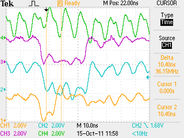
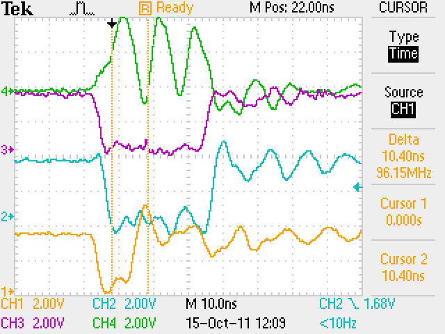
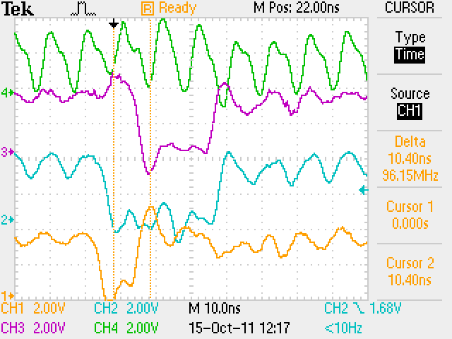
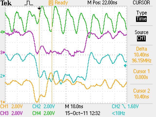
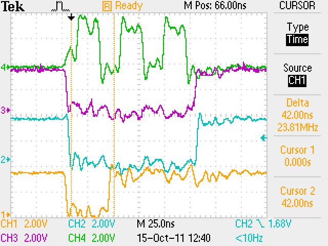
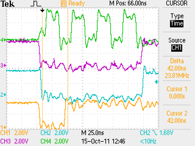
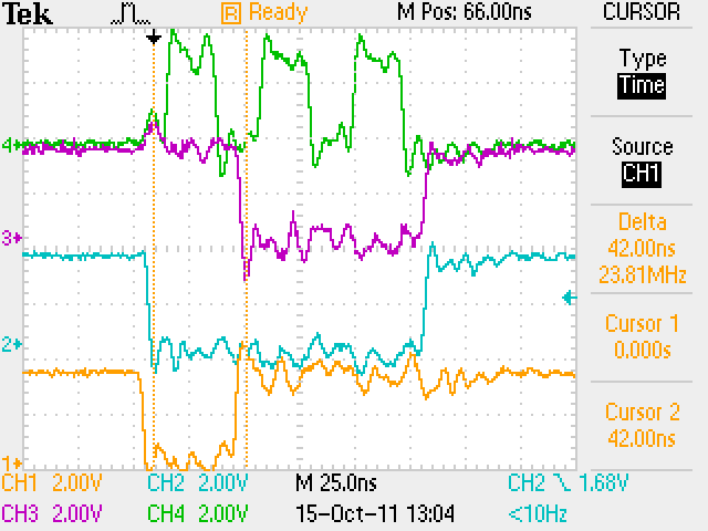
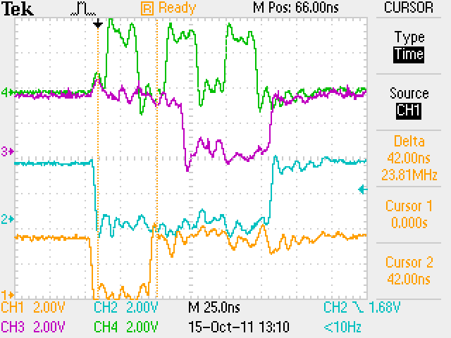
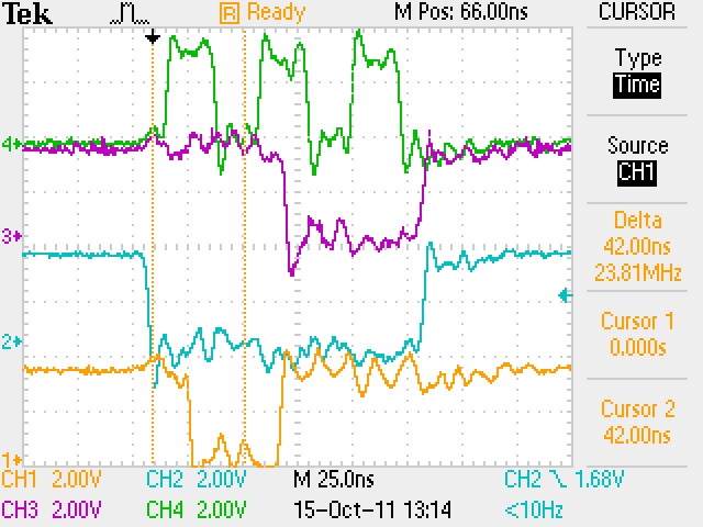
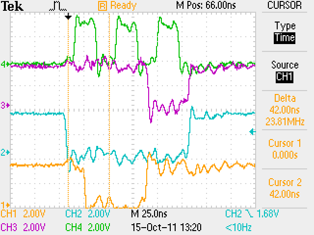
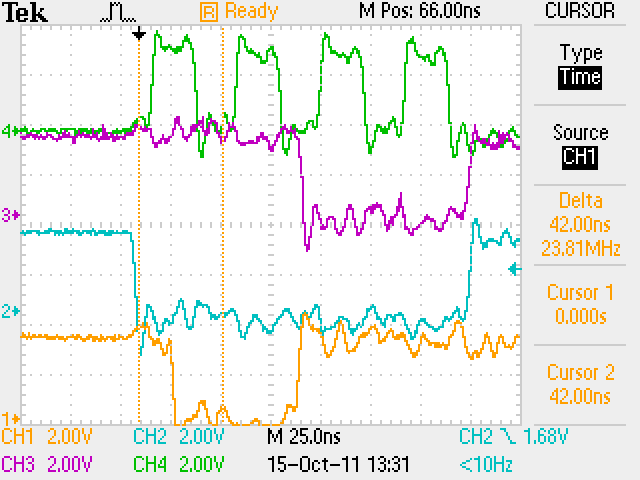